-
Please join our new sister site dedicated to discussion of gold, silver, platinum, copper and palladium bar, coin, jewelry collecting/investing/storing/selling/buying. It would be greatly appreciated if you joined and help add a few new topics for new people to engage in.
Bullion.Forum

You are using an out of date browser. It may not display this or other websites correctly.
You should upgrade or use an alternative browser.
You should upgrade or use an alternative browser.
DEEP CYCLE BATTERIES and BUSH POWER
- Thread starter condor22
- Start date

Help Support Prospecting Australia:
This site may earn a commission from merchant affiliate
links, including eBay, Amazon, and others.
condor22
Mike
So, I got into the van and car electrics to find out what the hell happened on my last trip to cause my needing a new van battery.
Simply - The Redarc BCDC input was from the Anderson connector to the car. The input and output positives (+) were fuse protected with inline fuse holders with 30A fuses as per Redarc's installation guide. However, they were sourced from Supercheap Auto. As I had no 12v power at the time I rewired back to OEM without any lights on and did not inspect the Redarc and associated wiring, I just disconnected it so the van 3 way fridge would work directly from the car and not from a BCDC1220 charged van battery.
This morning I did voltage checks through the system and found the Redarc output loom fuse holder had distorted and almost melted. So the reason for a new battery was that for almost an entire day the fridge was pulling 14amps and the battery wasn't being charged.
So back to the "drawing board", I'll leave the OEM wiring as is and tap the Redarc input from the Car input, (maybe) so that the fridge still runs from the car but at the same time allows some power to the charger. The van battery is switched and the fridge gets power from the car as do the lights in the van etc. regardless of the switch position. So if the van battery is isolated, the fridge is running from the car and the van battery gets topped up from the Redarc, the problem should not occur again.
I am seriously considering not reinstalling the Redarc at all, as I also have solar on the roof that would charge the van battery anyway (obviously not at night) or if I do reinstall the Redarc, switch it so that I can isolate if needed.
FYI - All of the wiring from the car battery, through the 70A continuous solenoid (IGN switched) to the Anderson and then the van is at least 6mm sq or bigger. Here are the voltage readings this morning.
Setup - van connected to car, engine on at idle, solar off, 240V off, lights on to give a load of 4.5 amps, battery was down to about 60% charge.
Results;
V at the start battery = 14.5v
V at the Anderson connector, rear bumper = 13.9v = a 0.6v drop
V at the terminals on the van transformer = 13.5v = another 0.4v drop
So a total of 1.0 volt drop. Of note - when the engine was off the load on the van battery was 4.5 amps, when the engine was on the BM PRO showed a 4.2 amp charge, so a net 8.7 amps going in. However as there is a motion detector on the van fridge, it would not use any power, so was not switched on. If I turn the battery off, this disconnects the car charging (without the Redarc)
The vehicle is a Holden Colorado and typically charges at 14.5 V.
- Joined
- Jul 20, 2016
- Messages
- 2,274
- Reaction score
- 2,272
So your fuse holders melted and you lost input power?
condor22
Mike
No, the fuse holder melted on the output of the charger to the battery. It was one I have had in the shed for a while and its cheapness coupled with the load of the fridge is what probably caused the problem.
In the mean time, I've decided to keep it simple and not reinstall the Redarc BCDC1220.
So, driving - The van battery will be switched off and isolated from all but the solar panels which will be on. That way any battery use from the previous day will be replaced while driving. As the Transformer also distributes the internal OEM 12 volt, when driving, the car will run the fridge as well as lights etc, when engine is on.
Even with a 1 volt drop, I'm happy with 13.5 volts at the van fridge.
I think assumption is the greatest problem here. I assumed what worked on my Toyota, would work on the Colorado, but given the voltage readings I got today, I should have checked this when I first changed vehicles = human error.
Edit, I detect mainly in winter, so stopping for 10-15 minutes won't cause the fridge temp to rise. If I stop for an hour or more, I'll switch to LPG for the break.
2nd edit, The other plus is, unlike the Redarc which stops charging when I stop, the solar will continue to charge.
Condor I'm pretty sure late Colorado has a "smart" alternator so indeed complete different scenario to your last vehicle. With a smart system charge voltage will vary depending on cruise, load and over run. In fact the charge rate is controlled by the battery sensor and engine ecu. Even fitting a different capacity battery to the vehicle can effect the vehicle charge and electrical system and hence note on Redarc BCDC use .....................that all additional electrical accessories must be grounded to the vehicle chassis or body, not to the main battery negative terminal, in order to be taken into account by the ECU. This type of alternator is even less capable of fully charging auxiliary batteries, and the use of the BCDC in these vehicles is imperative They also list the different BCDC models for the varying alternator types.
Given the above I would probably leave out the BM pro as it operates in basically the opposite in that all load must run thru it via the negative terminal of battery and not vehicle ground so will certainly throw a spanner in the works in that way. Basically like all and any computer controlled device if the vehicle senses any load / input that it cannot see or is not calibrated for it goes into confusion mode and in fact can effect many aspects of the vehicle electrical system not just the charge circuit. If you change battery capacity, along with the charge and discharge profile that is coded into the vehicle the system may not function correctly and the power management system may operate in fact in a limited operation mode.
The alternator ecu is controlling the charge characteristics for what it can see / sense but in fact the load etc is actually different and hence the poor thing becomes totally confused. From my limited knowledge on smart systems anything that is not connected via the vehicle earth / CAN bus then the charge control ecu cannot see it and hence cannot adjust as required accordingly.
I do a lot of work on fuel injection systems and have even had a vehicle once that couldn't work out why it was misfiring and running erratic. Turns out the engine cam angle sensor was picking up electrical flux from some other aftermarket wiring taped to loom and hence effecting the cam angle sensor ecu trigger signal. Shielded the offending wiring by wrapping it in alfoil then earthed it and hey presto ................ instant fix :Y: The bike that wouldn't run over 7 K and turned out the problem was a blown headlight Turns out the headlight globe is used as an earth ballast on that particular model. I only mention these scenarios as example of how the whole system can be effected by something one would not normally think is related to the vehicle problem. :N: Would appear that the intelligence and knowledge of the "grease monkey" has had to increase somewhat to keep pace with technology
  But hang on that's why we are not mechanics anymore .................. but have the new status of being a technician


As for technology ...................... ya gotta love it. I just did an alternator over run clutch pulley on a Mercedes van and the pulley alone cost more than the whole alternator for my old pajero Then there is the cost of the special puller to remove and refit required also .............. talk about opening a tin of worms and all to save a few bucks on fuel that the masses are always screaming for.
  Add the cost of production and supply of the extra components required along with additional cost to repair and maintain and I bet the consumers pocket is lighter still than before the "great idea"
Ok rant over
Given the above I would probably leave out the BM pro as it operates in basically the opposite in that all load must run thru it via the negative terminal of battery and not vehicle ground so will certainly throw a spanner in the works in that way. Basically like all and any computer controlled device if the vehicle senses any load / input that it cannot see or is not calibrated for it goes into confusion mode and in fact can effect many aspects of the vehicle electrical system not just the charge circuit. If you change battery capacity, along with the charge and discharge profile that is coded into the vehicle the system may not function correctly and the power management system may operate in fact in a limited operation mode.
The alternator ecu is controlling the charge characteristics for what it can see / sense but in fact the load etc is actually different and hence the poor thing becomes totally confused. From my limited knowledge on smart systems anything that is not connected via the vehicle earth / CAN bus then the charge control ecu cannot see it and hence cannot adjust as required accordingly.
I do a lot of work on fuel injection systems and have even had a vehicle once that couldn't work out why it was misfiring and running erratic. Turns out the engine cam angle sensor was picking up electrical flux from some other aftermarket wiring taped to loom and hence effecting the cam angle sensor ecu trigger signal. Shielded the offending wiring by wrapping it in alfoil then earthed it and hey presto ................ instant fix :Y: The bike that wouldn't run over 7 K and turned out the problem was a blown headlight
As for technology ...................... ya gotta love it. I just did an alternator over run clutch pulley on a Mercedes van and the pulley alone cost more than the whole alternator for my old pajero
Ok rant over
condor22
Mike
Thanks Bogger, These newer "smart" alternators are not my Forte. However, there is no issue with the caravan now as I'm not using the Redarc to charge the battery, only solar when driving.
I will look at the 4x4 Auxiliary though, although as the Engel draws much less current, it seems to be working ok, as do both BM PROs.
I will look at the 4x4 Auxiliary though, although as the Engel draws much less current, it seems to be working ok, as do both BM PROs.
condor22
Mike
Just got back from 5 weeks in the GT, all of which was off grid (except for 2 nights at Hard Hill CG Wedderburn)
Here are the results (electrical) from my trip, but first my usage.....
For ease of explanation, I'll start the day at 8 AM, when I checked battery level and turned off the diesel heater. Average consumption was 20% of battery capacity.
I have 1 x 130 AH AGM, so this equates to approx. 26 AH. On 2 occasions due to sub zero temps, the use was about 28%, or, approx. 36 AH.
I left the van to prospect with no 12 volt system operating and the solar panels on. (2 x 100 W flat mounted on the van roof). On return, approx. 4.30 PM, I turned off the panels and the battery, turned on the Honda Genny, along with the 15 A 240 VAC smart charger and the transformer. Turning off the battery disconnects the transformer charging circuit, which leaves the 15A charger to top up the battery under no load condition without interference from it, or the solar controller.
I ran the Honda for about 2 hours to a. operate the hot water system, b. ensure battery was fully charged and c. cook with microwave to save LPG.
After eating, washing dishes and showering, I turned off the Honda, switched off the 15 A charger and the transformer - and, switched the battery and solar panels back on so they charge from first light.
During the evening I watch about 4-5 hours of TV, have the diesel heater on from about 5 PM to 8 AM and the odd LED light. I also on occasion used the 12 VDC Laptop charger to operate from van battery, but usually without TV at the same time.
Conclusion - with a 3 way fridge on LPG my net use of 20% to say a max of 30% is being met by the 130 AH battery.
PS I also noted on a few occasions that my battery was almost fully charged from solar by mid afternoon, even on cloud covered, rainy "crappy" weather days.
Solar panels arrived today --12v 200 watt with solar charger controler attached... see picture.
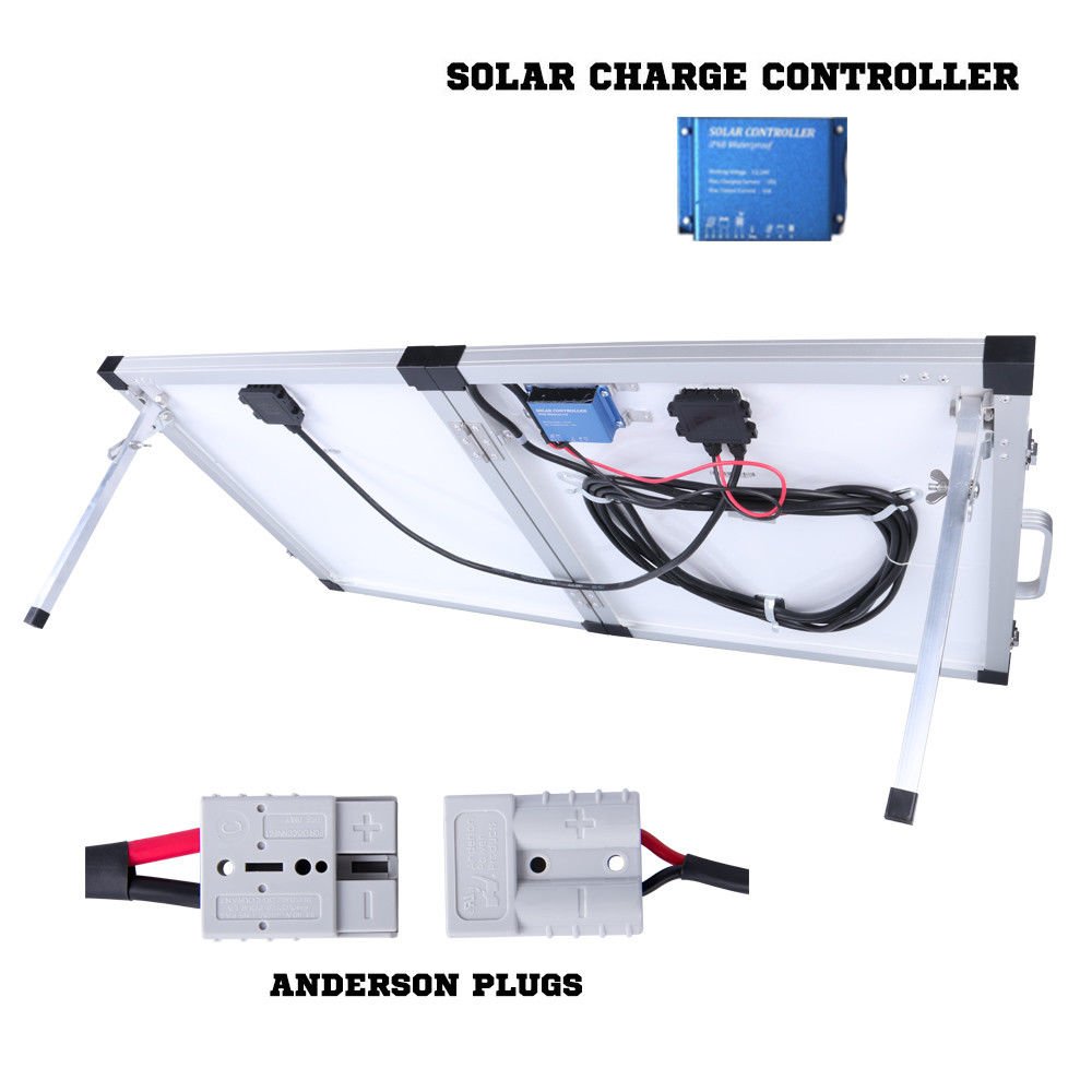
I want to by pass the controller that came with the panels and connect a controller that I can mount and monitor neat the battery in the camper.
I would appreciate any suggestions on how to do this, as I don't want to make any mistakes.
Would some thing like this would work ?
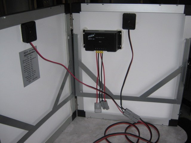

I want to by pass the controller that came with the panels and connect a controller that I can mount and monitor neat the battery in the camper.
I would appreciate any suggestions on how to do this, as I don't want to make any mistakes.
Would some thing like this would work ?

condor22
Mike
YES
I'm assuming you are using the blue controller, which looks like a Victron.
The closer a solar controller is to the battery, the less cable required, which minimises voltage drop.
I'd advise a correctly rated fuse or circuit breaker on either side of the controller. 200W could put out about 10-12 amps at the panel and the controller 14 amps. I have 10amp CCTBRKR on each panel (as individually they rate <10amps and a 20 amp fuse between controller and battery. Mine are fixed panels.
The plus in protecting individual panels is that if one fails at least you get half your daily ration which is better than none. They usually fail when you need them, not at home in the shed
condor22 said:YES
I'm assuming you are using the blue controller, which looks like a Victron.
The closer a solar controller is to the battery, the less cable required, which minimises voltage drop.
I'd advise a correctly rated fuse or circuit breaker on either side of the controller. 200W could put out about 10-12 amps at the panel and the controller 14 amps. I have 10amp CCTBRKR on each panel (as individually they rate <10amps and a 20 amp fuse between controller and battery. Mine are fixed panels.
The plus in protecting individual panels is that if one fails at least you get half your daily ration which is better than none. They usually fail when you need them, not at home in the shed
G'day condor
The blue controler on the panel is not a victron, its just what came with the panel.
It looks pretty basic and has no digital read out ..
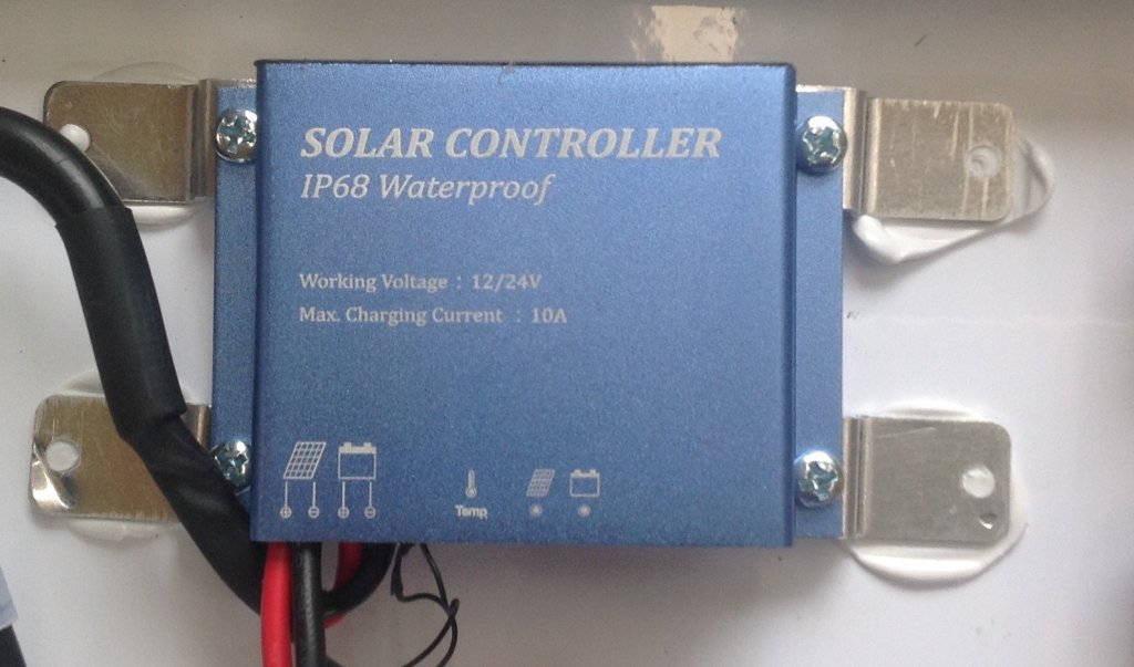
The panels are wired in paralel and then hard wired in to the input on the controller , the long 5 metre lead is also hard wired on the out put of the controller .. It has what looks like a rubberised seal underneath the controller to make it water proof.
Just not sure what way to do things ..and not mess it up ..
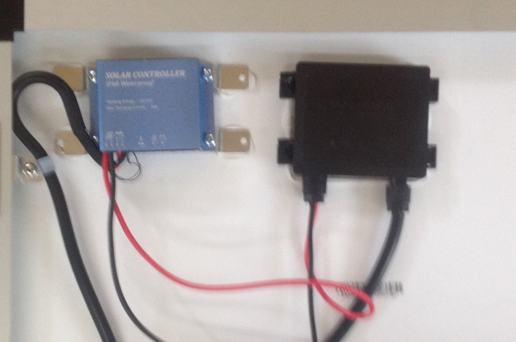
The black wire on the right conects the two panels together , the two red/black wires on the left, are wired into the small controller on the panel. The large black wire on the left of the picture is the out put wire to the battery ..
Should I cut or remove the wires from the controller ..and remove the controller its self from the back of the panel...?
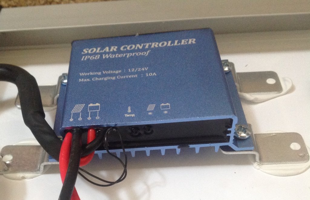
condor22
Mike
Strange, You say it's a 200W panel and the blue controller is rated at 10 amps. That's somewhat low for 200W of solar. I've measured my 2 x 100 W panels on my van at 14.6 amps.
However, leave the black cable that connects the 2 panels as is.
The red/black wire that goes from the right hand black box to the solar controller is the output to both halves and is the one to modify.
Where it me, I would cut the red and black wire at about half their length and put an Anderson plug on both of the cut ends. That way by joining the 2 plugs, the panel is as is and uses the inbuilt controller.
To feed the panel directly to another controller nearer your battery, you will need an extension lead with an Anderson plug on one end. Connect this to the Anderson plug that comes out of the right hand black box (panel output).
The other end would then be wired to the other solar controller input, either hard wired or if you wish it to be removable, Anderson plugs.
If this explanation still confuses, I'll draw you up a wiring diag.
Thanks condor
I think I understand what you mean ...
I will post a picture when I have conected the Anderson plugs .. :Y:
I think I understand what you mean ...
I will post a picture when I have conected the Anderson plugs .. :Y:
- Joined
- Jul 20, 2016
- Messages
- 2,274
- Reaction score
- 2,272
If you don't want to use that controller in the last pic just cut the input and output wires and connect them together (red,red, black,black)
Hook the other end up to the controller in the camper.
Leave a bit of wire (3cm?) on the controller to solder wires back on down the track if you want to use that controller again for some reason.
Hook the other end up to the controller in the camper.
Leave a bit of wire (3cm?) on the controller to solder wires back on down the track if you want to use that controller again for some reason.
Ok this is what I did.
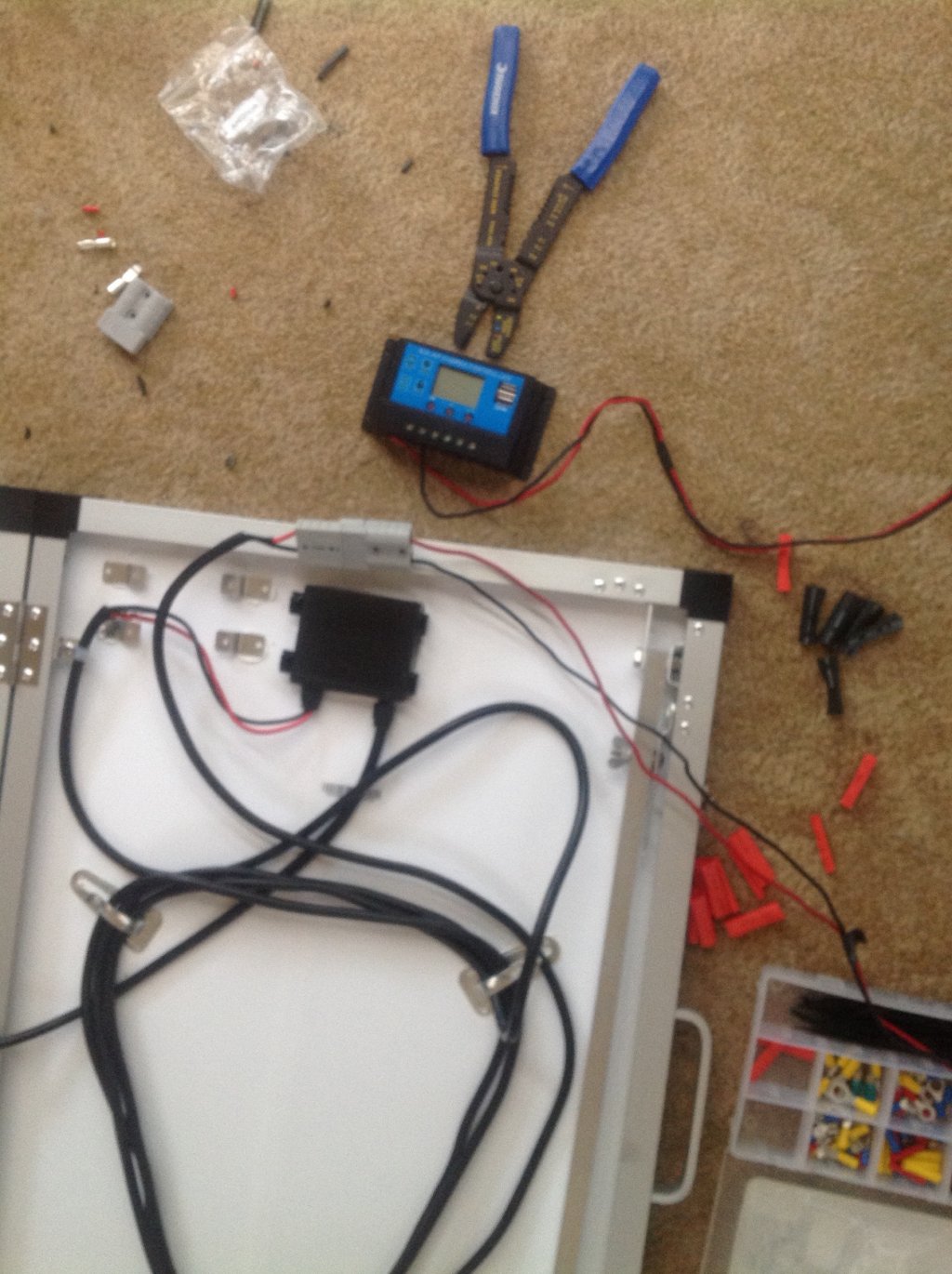

condor22
Mike
that'll do it 
Awesome. One step closercondor22 said:that'll do it
Have a question.
I have a 12 conection fuse block where the positive wire from the power source is attached to a single post terminal .
See picture here.
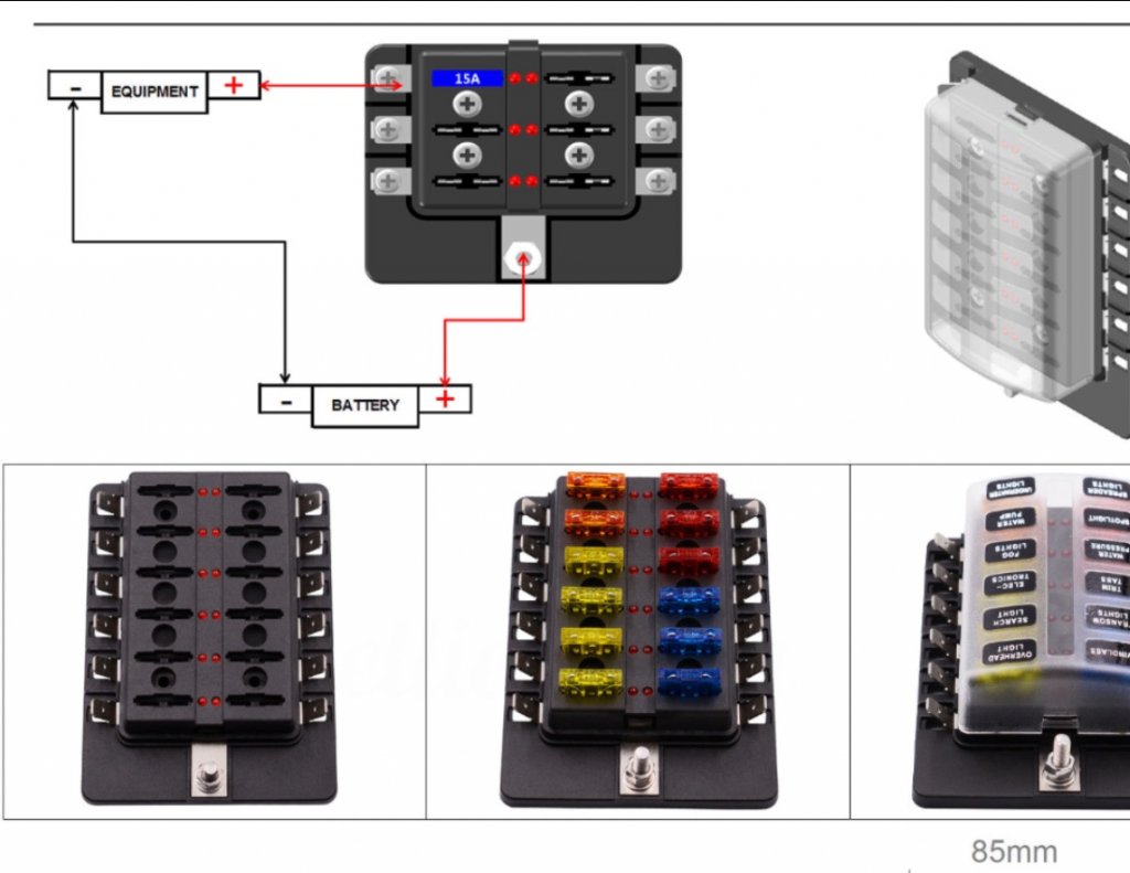
Im thinking, do I need to use a Ground Distribution block, so that I can connect the individual negative wires from LED lights,water pump, cig lighter , Usb etc to this grounding block and then one single heavy duty ground wire to the battery to complete the circuit ?
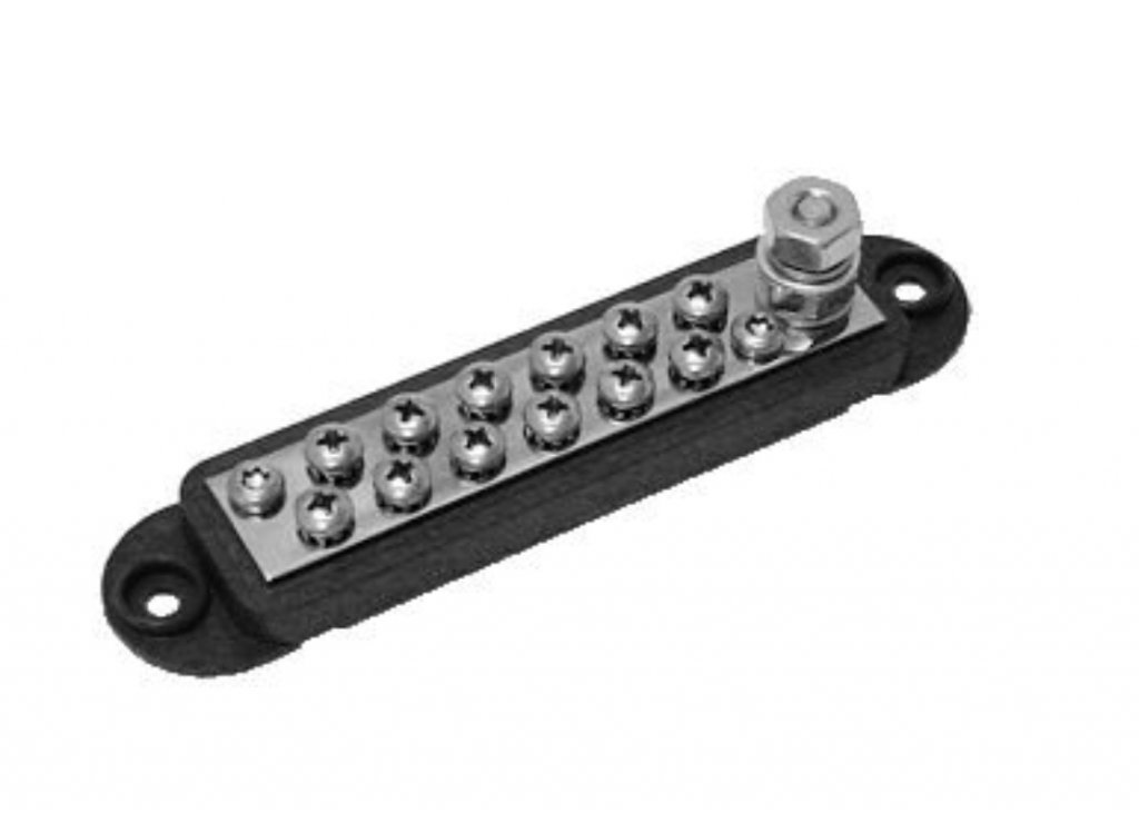
I have a 12 conection fuse block where the positive wire from the power source is attached to a single post terminal .
See picture here.

Im thinking, do I need to use a Ground Distribution block, so that I can connect the individual negative wires from LED lights,water pump, cig lighter , Usb etc to this grounding block and then one single heavy duty ground wire to the battery to complete the circuit ?

Probably don't need to get that elaborate as in use an earth distribution block ................... simply use an earth post and attach all earths to that, then a wire to battery neg from it. Same result just less components = kiss principle
Anything that will place a heavy load I run thru an individual large blade fuse holder, so one can get some decent wire size to it. More load again run through a circuit breaker.
The fuse block your showing would only use for light load applications.
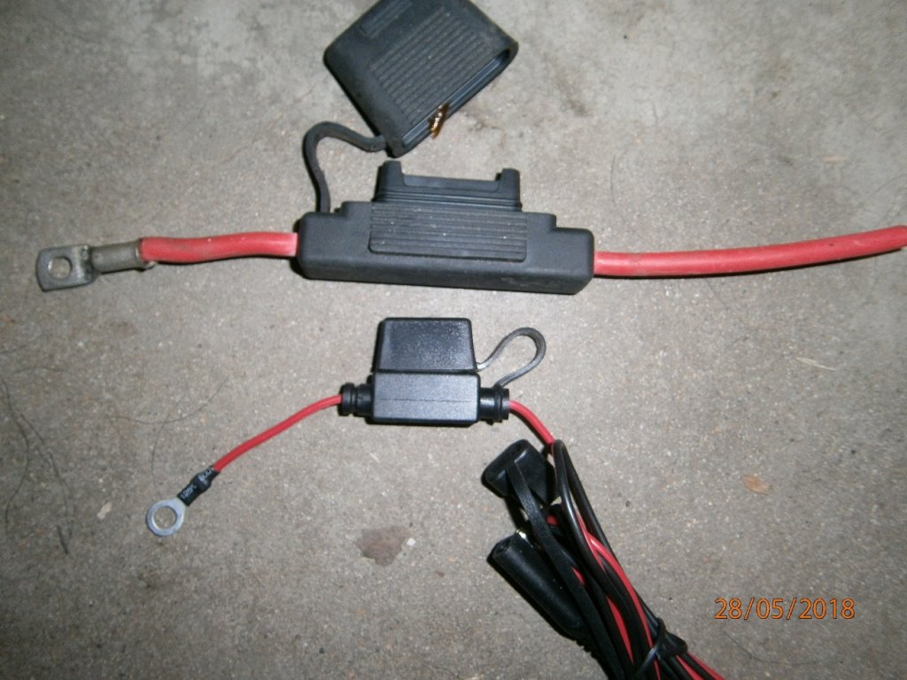
Anything that will place a heavy load I run thru an individual large blade fuse holder, so one can get some decent wire size to it. More load again run through a circuit breaker.
The fuse block your showing would only use for light load applications.

Similar threads
- Replies
- 10
- Views
- 3K
- Replies
- 39
- Views
- 14K


